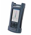
This E1/Datacom transmission analyzer is designed for performing
comprehensive analysis, measurement and evaluation of telecom
networks. It performs E1 frame data monitoring and analysis, dual
E1 channel testing, loop delay, APS delay, pulse measurement,
jitter measurement, signal level measurement. It also has many
enhanced test functions such as "PCM Simulator", "Mux/Demux",
"Drop & Insert" and "Network Tools". It is widely used in
R&D, production, installation, verification and maintenance
of SDH, PDH, PCM, DTU and Data protocol converter equipment.
- **0 &branded; balance and *5 &branded; unbalance line
interfaces
- HDB3 and AMI line codes
- Out-of-service framed and unframed testing
2 Mb/s, *4 Kb/s BER testing
Frame data and alarm monitoring
Clock slip measurement
- In-service framed and unframed testing
Hi-Z and through mode testing
CODE, FAS, CRC4, E-BIT BER testing
Frame data and timeslot activity monitoring
Monitoring of octet code in any selected timeslot
Built-in *4 kb/s tone channel monitoring capability
ABCD code monitoring in CAS signaling
TS*6 monitoring in CCS signaling
- Double E1 channel testing
Double E1 channels Rx Hi-Z and through mode testing
Double E1 channels Code, FAS, CRC*4, E-BIT BER testing
Double E1 channels FAS/NFAS, CAS Multi-frame, CCS timeslot *6
and timeslot activity monitoring
Double E1 channels timeslot data monitoring
Double E1 channels built-in *4 kb/s tone channel monitoring
capability
Double E1 channels CAS and CCS signaling monitoring
- Round trip delay measurement
- APS delay measurement
- Pulse Mask Measurement
Input E1 pulse shape display
Pulse width measurement
Pulse width and amplitude ratio measurement
Up-edge and down-edge time measurement
Overshoot and undershoot ratio measurement
Pulse amplitude and level measurement
- PCM simulator
Extensive error insertion and alarm generation
Frame data control and monitoring
Idle word insertion in one or more timeslots with
programmable pattern
VF tone generation and measurement in one or more timeslots
Listen to any voice channel in the receiver via earphone
Talk to any voice channel in the transmitter via microphone
Perform the tests of signal level and frequency of the VF
channel simultaneously
CAS and CCS signaling generation and monitoring
- Frequency and Offset measurements
- Level measurement
- Transmit clock deviation up to **9ppm
- Clock source: Internal, Interface and External 2 M
clock/signal
- Testing pattern: PRBS, Fixed Code, **-BIT User-programmable
word
- Error insertion: Single and Fixed Rate
- Real-time transmit circuit status indication: open/short
- Manual or auto-timer measurements
- Performance analysis according to G.**1, G.**6, and M.***0
- Option 1: Jitter Testing
Peak-to-peak jitter measurement
Jitter measurement comply with O.**2 filter
Hit seconds and hit free seconds counts
- Option 2: Datacom Testing
Datacom (V.*4, V.*5, V.*6, X.*1, RS***9, RS***5, EIA***0 and
EIA***0A) BER testing
Asynchronous BER testing at a baud rate range of *0 b/s to
*7.6 b/s
Synchronous BER testing at a data rate of 1.2 kb/s to ***8
kb/s
DTE or DCE equipment emulation
Synchronous clock source selectable
Frequency measurement
Handshaking signals control and monitoring
- Option 3: G.**3 *4 kb/s CO Testing
G.**3 *4 kb/s Co-directional BER testing
Octet timing control and monitoring
Frequency and offset measurement
Transmit clock source: Internal and Interface
- Option 4: Mux & Demux Testing
E*-Datacom synchronous *4 kb/s, N¡*4 kb/s BER testing
E*-G.**3 CO synchronous *4 kb/s BER testing
Frequency and Offset measurement of Rx interface
Handshaking signals monitoring of Datacom interface
E1 framed data and alarm monitoring
- Option 5: Drop & Insert Testing
Insert mode: Insert synchronous *4 k, Nx*4 kb/s data from
Datacom or G.**3 CO interface to one or more timeslots of E1
signal
Drop mode: Drop one or more timeslots data from E1 signal to
Datacom or G.**3 CO interface
Insert Drop mode: Insert and drop one or more E1 timeslots
data from or to Datacom or G.**3 CO interface


gmail com")

